Description
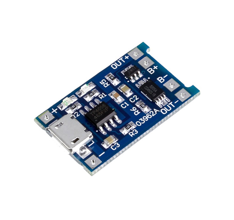
TP4056 1A Li-Ion Battery Charging Board Micro USB with Current Protection is a tiny module, perfect for charging single cell 3.7V 1 Ah or higher lithium-ion (Li-Ion) cells such as 16550s that don’t have their own protection circuit. Based on the TP4056 charger IC and DW01 battery protection IC this module will offer 1A charge current then cut off when finished.

Furthermore, when the battery voltage drops below 2.4V the protection IC will switch the load off to protect the cell from running at too low of a voltage – and also protects against over-voltage and reverse polarity connection (it will usually destroy itself instead of the battery) however please check you have it connected correctly the first time.
 Manufactured under fully machinery processing. In conclusion, it is a special design for a single lithium battery charging. TP4056 Other features include the current monitor, under-voltage lockout, automatic recharge, and two status pins to indicate charge termination and the presence of an input voltage.
Using the module:
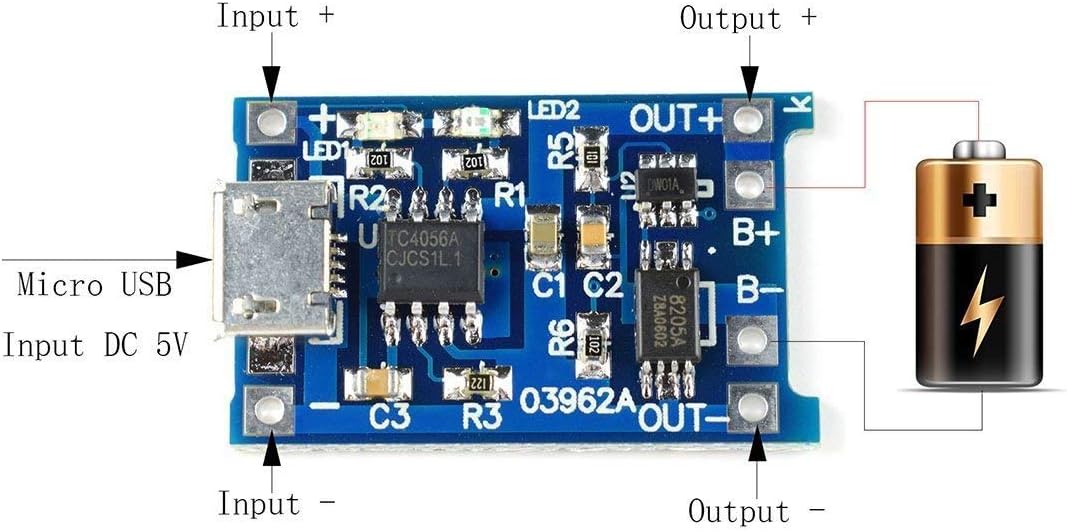
- Connect micro USB cable for power, or 5V DC to pads marked IN+ and IN- on the left-hand side of the module
- Connect cell to charge to B+/B- pads on the right-hand side of the module.
- A load (something for the battery to power) can be connected to the OUT+/OUT- pads on the right-hand side
- Important! Disconnect load when charging
- The red LED indicates charging in progress, the green LED indicates charging has finished.
- Never charge your battery at a rate greater than 1C.
Note:
1. When the first time you access the battery, there may be no voltage output between OUT- and OUT +, at this time, get access to the 5V voltage, it will be activated.
2. When the battery was getting out from B + and B-, it still needs to be charged then can be activated.
3. If you want to use a phone charger to charge, the current input should be up to 1A and more, otherwise, it can not be in normal charge.
Connect the battery to the B + and B-, insert the phone charger into the USB female, red light means being charged, the green light means full charged.


Reviews
There are no reviews yet.